
Compiling ZPU application
$id$
The worlds smallest 32 bit CPU with GCC toolchain
This CPU is finding a new home at www.opencores.org, please contact me if you are willing and able to help in shaping up the www.opencores.org pages.
The HDL, GCC toolchain and eCos HAL are actually done. Mainly I could need a hand with writing up docs/web pages/examples/bug reports.
The ZPU has a BSD license for the HDL and GPL for the rest(source files are sadly out of date here, patches gladly accepted!). This allows deployments to implement any version of the ZPU they want without running into commercial problems, but if improvements are done to the architecture as such, then they need to be contributed back.
One strength of the ZPU is that it is tiny and therefore easy to implement from scratch to suit specialized needs and optimizations.
Currently there exists some pages at http://www.zylin.com/zpu.htm that explains about the ZPU. According to OpenCores policy this information should be moved to www.opencores.org. Patches gratefully accepted to do so!
Per Jan 1. 2008, Zylin has the Copyright for the ZPU, i.e. Zylin is free to decide that the ZPU shall have a BSD license for HDL + GPL for the rest.
Sincerley,
Øyvind Harboe
Zylin AS
Features
Small size: 442 LUT @ 95 MHz after P&R w/32 bit datapath Xilinx XC3S400
Wishbone
Code size 80% of ARM Thumb
GCC toolchain(GDB, newlib, libstdc+)
eCos embedded operating system support
Survey
Please take the time to fill in this short survey so we can gather information about where the ZPU can be the most useful:
http://www.zylin.com/zpusurvey.html
Status
HDL works
GCC toolchain works
eCos HAL works, but could be less RAM hungry
The main problem at this point is not usage of the CPU, but that the documentation/CVS layout needs attention
Needs GDB stub support in eCos
Could do with a Verilog implementation(ca. 600 lines to translate)
Simulator
The ZPU simulator is integrated into the Zylin Embedded CDT plugin to ease debugging of ZPU applications:
http://www.zylin.com/embeddedcdt.html
The ZPU simulator has many features besides debugging an application:
taking output from simulation(e.g. ModelSim) and matching that against the Java simulator, thus making it much easier to debug HDL implementations and also getting real world timing information
can generate gprof output
generate various statistics
The plugin is still pretty rough around the edges, and needs to get GUI support for enabling the ModelSim trace input feature.
Compiling
ZPU application

Setting
up the simulator
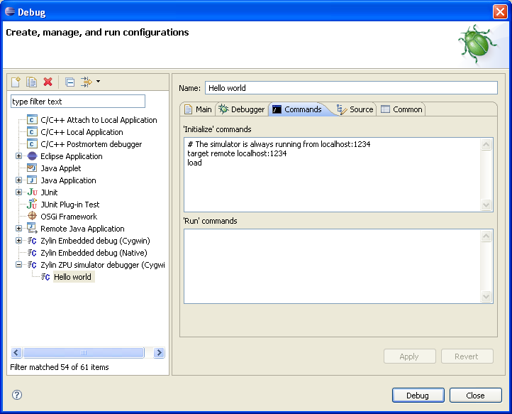
Choosing
ZPU executable

Debug
session
You'll find a working simulation script in hdl/example/simzpu_small.do and hdl/example_medium/simzpu_medium.do, which show simulation of the small(zpu_core_small.vhd) and medium sized ZPU(zpu_core.vhd). hdl/example/simzpu_interrupt.do shows use of interrupts.
When implementing the ZPU, copy the following files and modify them to your needs:
../install/bin/zpu-elf-objcopy -O binary hello.elf hello.bin

java -classpath ../simulator/zpusim.jar com.zylin.zpu.simulator.tools.MakeRam hello.bin >hello.bram
cd zpu/roadshow/roadshow/dhrystone
sh build.sh
cd zpu/hdl/example
gcc zpuromgen.c
$ ./a
Usage: ./a binary_file
./a ../../roadshow/roadshow/dhrystone/dhrystone.bin >app.txt
Copy and paste app.txt into helloworld.vhd.
After running the hello world simulation (see zpusim.do), two files are written to the hdl/example directory:
cd zpu/sw/helloworld

../install/bin/zpu-elf-gcc -phi hello.c -o hello.elf
java -classpath ../simulator/zpusim.jar -Xmx512m com.zylin.zpu.simulator.Phi 4444

../install/bin/zpu-elf-gdb hello.elf
(gdb) target remote localhost:4444

(gdb) load

(gdb) continue

Example:
		IM 5                ; push 5 onto the stack
		LOADSP 20           ; push value at memory location SP+20
		ADD                 ; pop 2 values on the stack and push the result
The choice of opcodes is intimately tied to the GCC toolchain capabilities.
/* simple program showing some interesting qualities of the ZPU toolchain */
void bar(int);
int j;
void foo(int a, int b, int c)
{
a++;
b+=a;
j=c;
bar(b);
}
foo:
loadsp 4 ; a is at memory location SP+4
im 1
add
loadsp 12 ; b is now at memory location SP+12
add
loadsp 16 ; c is now at memory location SP+16
im 24 ; �j� is at absolute memory location 24.
; Notice how the ZPU toolchain is using link-time relaxation
; to squeeze the address into a single no-op
store
im 22 ; the fn bar is at address 22
call
im 12
return ; 12 bytes of arguments + return from fn
| Name | Opcode | Description | Definition |
| BREAKPOINT | 00000000 | The debugger sets a memory location to this value to set a breakpoint. Once a JTAG-like debugger interface is added, it will be convenient to be able to distinguish between a breakpoint and an illegal(possibly emulated) instruction. | No effect on registers |
| IM | 1xxx xxxx |
Pushes 7 bit sign extended integer and sets the a �instruction decode interrupt mask� flag(IDIM).
If the IDIM flag is already set, this instruction shifts the value on the stack left by 7 bits and stores the 7 bit immediate value into the lower 7 bits. Unless an instruction is listed as treating the IDIM flag specially, it should be assumed to clear the IDIM flag. To push a 14 bit integer onto the stack, use two consequtive IM instructions. If multiple immediate integers are to be pushed onto the stack, they must be interleaved with another instruction, typically NOP. |
pc <= pc + 1
|
| STORESP | 010x xxxx | Pop value off stack and store it in the SP+xxxxx*4 memory location, where xxxxx is a positive integer. | |
| LOADSP | 011x xxxx | Push value of memory location SP+xxxxx*4, where xxxxx is a positive integer, onto stack. | |
| ADDSP | 0001 xxxx | Add value of memory location SP+xxxx*4 to value on top of stack. | |
| EMULATE | 001x xxxx |
Push PC to stack and set PC to 0x0+xxxxx*32. This is used to emulate opcodes. See
zpupgk.vhd for list of emulate opcode values used. zpu_core.vhd contains
reference implementations of these instructions rather than letting the ZPU execute the EMULATE instruction
One way to improve performance of the ZPU is to implement some of the EMULATE instructions. |
|
| PUSHPC | emulated | Pushes program counter onto the stack. | |
| POPPC | 0000 0100 | Pops address off stack and sets PC | |
| LOAD | 0000 1000 |
Pops address stored on stack and loads the value of that address onto stack.
Bit 0 and 1 of address are always treated as 0(i.e. ignored) by the HDL implementations and C code is guaranteed by the programming model never to use 32 bit LOAD on non-32 bit aligned addresses(i.e. if a program does this, then it has a bug). |
|
| STORE | 0000 1100 |
Pops address, then value from stack and stores the value into the memory location of the address.
Bit 0 and 1 of address are always treated as 0 |
|
| PUSHSP | 0000 0010 | Pushes stack pointer. | |
| POPSP | 0000 1101 | Pops value off top of stack and sets SP to that value. Used to allocate/deallocate space on stack for variables or when changing threads. | |
| ADD | 0000 0101 | Pops two values on stack adds them and pushes the result | |
| AND | 0000 0110 | Pops two values off the stack and does a bitwise-and & pushes the result onto the stack | |
| OR | 0000 0111 | Pops two integers, does a bitwise or and pushes result | |
| NOT | 0000 1001 | Bitwise inverse of value on stack | |
| FLIP | 0000 1010 |
Reverses the bit order of the value on the stack, i.e. abc->cba, 100->001, 110->011, etc.
The raison d'etre for this instruction is mainly to emulate other instructions. |
|
| NOP | 0000 1011 | No operation, clears IDIM flag as side effect, i.e. used between two consequtive IM instructions to push two values onto the stack. | |
| PUSHSPADD | 61 |
a=sp; b=popIntStack()*4; pushIntStack(a+b); |
|
| POPPCREL | 57 | setPc(popIntStack()+getPc()); | |
| SUB | 49 |
int a=popIntStack(); int b=popIntStack(); pushIntStack(b-a); |
|
| XOR | 50 | pushIntStack(popIntStack() ^ popIntStack()); | |
| LOADB | 51 |
8 bit load instruction. Really only here for compatibility with
C programming model. Also it has a big impact on DMIPS test.
pushIntStack(cpuReadByte(popIntStack())&0xff); |
|
| STOREB | 52 |
8 bit store instruction. Really only here for compatibility with
C programming model. Also it has a big impact on DMIPS test.
addr = popIntStack(); |
|
| LOADH | 34 |
16 bit load instruction. Really only here for compatibility with
C programming model.
pushIntStack(cpuReadWord(popIntStack())); |
|
| STOREH | 35 |
16 bit store instruction. Really only here for compatibility with
C programming model.
addr = popIntStack(); |
|
| LESSTHAN | 36 |
Signed comparison a = popIntStack(); b = popIntStack(); pushIntStack((a < b) ? 1 : 0); |
|
| LESSTHANOREQUAL | 37 |
Signed comparison a = popIntStack(); b = popIntStack(); pushIntStack((a <= b) ? 1 : 0); |
|
| ULESSTHAN | 37 |
Unsigned comparison long a;//long is here 64 bit signed integer long b; a = ((long) popIntStack()) & INTMASK; // INTMASK is unsigned 0x00000000ffffffff b = ((long) popIntStack()) & INTMASK; pushIntStack((a < b) ? 1 : 0); |
|
| ULESSTHANOREQUAL | 39 |
Unsigned comparison long a;//long is here 64 bit signed integer long b; a = ((long) popIntStack()) & INTMASK; // INTMASK is unsigned 0x00000000ffffffff b = ((long) popIntStack()) & INTMASK; pushIntStack((a <= b) ? 1 : 0); |
|
| EQBRANCH | 55 |
int compare; int target; target = popIntStack() + pc; compare = popIntStack(); if (compare == 0) { setPc(target); } else { setPc(pc + 1); } |
|
| NEQBRANCH | 56 |
int compare; int target; target = popIntStack() + pc; compare = popIntStack(); if (compare != 0) { setPc(target); } else { setPc(pc + 1); } |
|
| MULT | 41 |
Signed 32 bit multiply pushIntStack(popIntStack() * popIntStack()); |
|
| DIV | 53 |
Signed 32 bit integer divide. a = popIntStack(); b = popIntStack(); if (b == 0) { // undefined } pushIntStack(a / b); |
|
| MOD | 54 |
Signed 32 bit integer modulo. a = popIntStack(); b = popIntStack(); if (b == 0) { // undefined } pushIntStack(a % b); |
|
| LSHIFTRIGHT | 42 |
unsigned shift right. long shift; long valX; int t; shift = ((long) popIntStack()) & INTMASK; valX = ((long) popIntStack()) & INTMASK; t = (int) (valX >> (shift & 0x3f)); pushIntStack(t); |
|
| ASHIFTLEFT | 43 |
arithmetic(signed) shift left. long shift; long valX; shift = ((long) popIntStack()) & INTMASK; valX = ((long) popIntStack()) & INTMASK; int t = (int) (valX << (shift & 0x3f)); pushIntStack(t); |
|
| ASHIFTRIGHT | 43 |
arithmetic(signed) shift left. long shift; int valX; shift = ((long) popIntStack()) & INTMASK; valX = popIntStack(); int t = valX >> (shift & 0x3f); pushIntStack(t); |
|
| CALL | 45 |
call procedure. int address = pop(); push(pc + 1); setPc(address); |
|
| CALLPCREL | 63 |
call procedure pc relative int address = pop(); push(pc + 1); setPc(address+pc); |
|
| EQ | 46 | pushIntStack((popIntStack() == popIntStack()) ? 1 : 0); | |
| NEQ | 48 | pushIntStack((popIntStack() != popIntStack()) ? 1 : 0); | |
| NEG | 47 | pushIntStack(-popIntStack()); |
The startup code is found in the GCC source code under gcc/libgloss/zpu, but to make the startup code more available, it has been duplicated into zpu/sw/startup
To minimize startup size, see codesize demo. This is pretty standard GCC stuff and simple enough once you've been over it a couple of times.
Implementing a ZPU can be done without understanding the toolchain in detail, i.e. using exclusively HDL skills and only a rudimentary understanding of standard GCC/GDB usage is sufficient.
A few tips:
| Address | Name | Description |
| 0x000 | Reset |
1.When the ZPU boots, this is the first instruction to be executed.
2.The stack pointer is initialised to maximum RAM address |
| 0x020 | Interrupt | This is the entry point for interrupts. |
| 0x040- | Emulated instructions | Emulated opcode 34. Note that opcode 32 and opcode 33 are not normally used to emulate instructions as these memory addresses are already used by boot vector, GCC registers and the interrupt vector. |
|
Address |
Type |
Name |
Description |
|
0x080A0000 |
Write |
ZPU enable |
Bit [31:1] Not used Bit [0] Enable ZPU operations 0 ZPU is held in Idle mode 1 ZPU running |
|
0x080A000C |
Read/ Write |
ZPU Debug channel / UART to ARM7 TX NOTE! ZPU side |
Bit [31:9] Not used Bit [8] TX buffer ready (valid on ready) 0 TX buffer not ready (full) 1 TX buffer ready Bit [7:0] TX byte (valid on write) |
|
0x080A0010 |
Read |
ZPU Debug channel / UART to ARM7 RX NOTE! ZPU side |
Bit [31:9] Not used Bit [8] RX buffer data valid 0 RX buffer not valid 1 RX buffer valid Bit [7:0] RX byte (when valid) |
|
0x080A0014 |
Read/ Write |
Counter(1) |
Bit [0] Reset counter (valid for write) 0 N/A 1 Reset counter Bit [1] Sample counter (valid for write) 0 N/A 1 Sample counter Bit [31:0] Counter bit 31:0 |
|
0x080A0018 |
Read |
Counter(2) |
Bit [31:0] Counter bit 63:32 |
|
0x080A0020 |
Read / Write |
Global_Interrupt_mask |
Bit [31:1] Not used Bit [0] Global intr. Mask 0 Interrupts enabled 1 Interrupts disabled |
|
0x080A0024 |
Write |
UART_INTERRUPT_ENABLE |
Bit [31:1] Not used Bit [0] Debug channel / UART RX interrupt enable 0 Interrupt disable 1 Interrupt enable |
|
0x080A0028 |
Read Write |
UART_interrupt |
Bit [31:1] Not used Bit [0] Debug channel / UART RX interrupt pending (Read) 0 No interrupt pending 1 Interrupt pending Bit [0] Clear UART interrupt (Write) 0 N/A 1 Interrupt cleared |
|
0x080A002C |
Write |
Timer_Interrupt_enable |
Bit [31:1] Not used Bit [0] Timer interrupt enable 0 Interrupt disable 1 Interrupt enable |
|
0x080A0030 |
Read / Write |
Timer_interrupt |
Bit [31:2] Not used Bit [0] Timer interrupt pending (Read) 0 No interrupt pending 1 Interrupt pending Bit [1] Reset Timer counter (Write) 0 N/A 1 Timer counter reset Bit [0] Clear Timer interrupt (Write) 0 N/A 1 Interrupt cleared |
|
0x080A0034 |
Write |
Timer_Period |
Bit [31:0] Interrupt period (write) Number of clock cycles between timer interrupts NOTE! The timer will start at Timer_Periode value and count down to zero, and generate an interrupt |
|
.0x080A0038 |
Read |
Timer_Counter |
Bit [31:0] Timer counter (read)
|
|
|
|
|
|
|
|
|
|
|
|
|
|
|
|
|
|
|
|
|
However this wishbone bridge was used together with the hdl/zy2000 implementation of the ZPU, which differs slightly from hdl/zpu4/core.
The ZY2000 is a complete implementation of the ZPU including: DRAM, soft-MAC, wishbone bridges, GPIO subsystem, etc. This also included an eCos HAL w/TCP/IP support.
There are two debug modes in which the ZY1000 can operate:
To trigger an interrupt, the interrupt signal must be asserted. The ZPU does not define any interrupt disabling mechanism, this must be implemented by the interrupt controller and controlled via memory mapped IO.
Interrupts are masked when the IDIM flag is set, i.e. with consequtive IM instructions.
The ZPU has an edge triggered interrupt. As the ZPU notices that the interrupt is asserted, it will execute the interrupt instruction. The interrupt signal must stay asserted until the ZPU acknowledges it.
When the interrupt instruction is executed, the PC will be pushed onto the stack and the PC will be set to the interrupt vector address (0x20).
Note that the GCC compiler requires three registers r0,r1,r2,r3 for some rather uncommon operations. These 32 registers are mapped to memory locations 0x0, 0x4, 0x8, 0xc. The default interrupt vector at address 0x20 will load the value of these memory locations onto the stack, call _zpu_interrupt and restore them.
See zpu/hdl/zpu4/test/interrupt/ for C code and zpu/hdl/example/simzpu_interrupt.do for simulation example.
It uses a BRAM (dual port RAM w/read/write to both ports) as data & code storage and is implemented as a simple state machine.
Essentially it has three states:
Achieving above 50-100 DMIPS with the current ZPU architecture is probably a non-starter and a more conventional RISC design makes more sense here.
The unique advantages of the ZPU is size in terms of HDL & code size.
The point is that characters(bytes) are sent to/from the ZPU via some terminal.
The ZPU defines in the memory map a UART / debug channel. This should be implemented by some suitable debug channel for the device in which the ZPU is implemented.
www.opencores.org has several UART implementations. This is one of the simpler ones: http://www.opencores.org/projects.cgi/web/uart/overview
Secondly you should write a small HDL module that interface between the ZPU memory map of debug channel to the UART. This should be relatively simple as all you need to do is to let the ZPU query the FIFO in/out for busy flag and allow the ZPU to read/write data to the UART via the memory map.
It performs better(despite having less memory bandwidth than zpu_core_small.vhd) since it implements many more instructions.
| Symbol | Direction | Bit width | Purpose |
|---|---|---|---|
| adr | Input | 24 | Address where to read from SPI |
| dat_o | Output | 32 | Data read from SPI |
| clk | Input | 1 | Input clock. Used for both interface and SPI |
| ce | Input | 1 | Chip Enable |
| rst | Input | 1 | Asynchronous reset |
| ack | Output | 1 | Data valid ACK |
| SPI_CLK | Output | 1 | SPI output clock |
| SPI_MOSI | Output | 1 | SPI output data from controller to chip |
| SPI_MISO | Input | 1 | SPI input data from chip to controller |
| SPI_SELN | Output | 1 | SPI nSEL (deselect, active low) signal |
The generics for the Zealot Medium ZPU are:
zpu-elf-gcc -Os -abel smallstd.c -o smallstd.elf -Wl,--relax -Wl,--gc-sections

zpu-elf-size small.elf


$ zpu-elf-size small.elf

   text    data     bss     dec     hex filename

   2845     952      36    3833     ef9 small.elf
zpu-elf-gcc -Os -abel crt0_phi.S small.c -o small.elf -Wl,--relax -Wl,--gc-sections -nostdlib

zpu-elf-size small.elf


$ zpu-elf-size small.elf

   text    data     bss     dec     hex filename

     56       8       0      64      40 small.elf
tar -xjvf ecossnapshot.tar.bz2

tar -xjvf repository.tar.bz2

tar -xjvf ecostools.tar.bz2

# run this every time you open the shell

export PATH=$PATH:`pwd`/ecos-install

export ECOS_REPOSITORY=`pwd`/ecos/packages:`pwd`/repository
ecosconfig new zeta default

ecosconfig tree

make

cd kernel/current

make tests
$ zpu-elf-size *

   text    data     bss     dec     hex filename

  15761    1504   12060   29325    728d bin_sem0

  16907    1512   14436   32855    8057 bin_sem1

  17105    1524   30032   48661    be15 bin_sem2

  17186    1512   14436   33134    816e bin_sem3

  18986    1500   12036   32522    7f0a clock0

  15812    1504   13236   30552    7758 clock1

  25095    1972   13224   40291    9d63 clockcnv

  16437    1500   13224   31161    79b9 clocktruth

  15762    1504   12060   29326    728e cnt_sem0

  17124    1512   14436   33072    8130 cnt_sem1

  35947    1564   22512   60023    ea77 dhrystone

  16428    1500   13228   31156    79b4 except1

  15751    1504   12052   29307    727b flag0

  19145    1512   15624   36281    8db9 flag1

  20053    1516  102908  124477   1e63d fptest

  15998    1496   12092   29586    7392 intr0

  16080    1496   12200   29776    7450 kalarm0

  15327    1496   12036   28859    70bb kcache1

  15549    1496   13224   30269    763d kcache2

  18291    1500   12260   32051    7d33 kclock0

  16231    1500   13232   30963    78f3 kclock1

  16572    1496   13228   31296    7a40 kexcept1

  15618    1496   12060   29174    71f6 kflag0

  19287    1500   15624   36411    8e3b kflag1

  16887    1516   15628   34031    84ef kill

  16186    1496   12128   29810    7472 kintr0

  19724    1504   14516   35744    8ba0 klock

  18283    1500   14592   34375    8647 kmbox1

  15539    1496   12064   29099    71ab kmutex0

  16524    1504   15664   33692    839c kmutex1

  18272    1712   20348   40332    9d8c kmutex3

  18682    1608   20352   40642    9ec2 kmutex4

  15619    1496   14412   31527    7b27 ksched1

  15567    1496   12060   29123    71c3 ksem0

  17063    1500   14436   32999    80e7 ksem1

  15504    1496   13228   30228    7614 kthread0

  16167    1496   14412   32075    7d4b kthread1

  18281    1512   14580   34373    8645 mbox1

  20611    1508   14940   37059    90c3 mqueue1

  15672    1504   12064   29240    7238 mutex0

  16678    1516   15664   33858    8442 mutex1

  17694    1508   16868   36070    8ce6 mutex2

  18203    1720   20344   40267    9d4b mutex3

  16352    1508   14428   32288    7e20 release

  15890    1500   14412   31802    7c3a sched1

  44196    1612  286332  332140   5116c stress_threads

  17891    1524   16864   36279    8db7 sync2

  16943    1512   15644   34099    8533 sync3

  15467    1496   13064   30027    754b thread0

  16134    1496   14420   32050    7d32 thread1

  17560    1512   15636   34708    8794 thread2

  16279    1500   24028   41807    a34f thread_gdb

  17051    1504   20376   38931    9813 timeslice

  17146    1504   21564   40214    9d16 timeslice2

  37313    1512  422380  461205   70995 tm_basic
$ arm-elf-size *

   text    data     bss     dec     hex filename

  25204     692   16976   42872    a778 bin_sem0

  26644     700   22096   49440    c120 bin_sem1

  26996     712   55584   83292   1455c bin_sem2

  27008     700   22100   49808    c290 bin_sem3

  28992     688   16944   46624    b620 clock0

  25456     692   19532   45680    b270 clock1

  34572    1160   19520   55252    d7d4 clockcnv

  26224     688   19508   46420    b554 clocktruth

  25204     692   16976   42872    a778 cnt_sem0

  26888     700   22108   49696    c220 cnt_sem1

  44180     752   27416   72348   11a9c dhrystone

  26088     688   19520   46296    b4d8 except1

  25236     692   16968   42896    a790 flag0

  29532     700   24668   54900    d674 flag1

  29508     704  109652  139864   22258 fptest

  25932     684   17016   43632    aa70 intr0

  25824     684   17112   43620    aa64 kalarm0

  24728     684   16956   42368    a580 kcache1

  25168     684   19512   45364    b134 kcache2

  28112     688   17168   45968    b390 kclock0

  25976     688   19524   46188    b46c kclock1

  26372     684   19512   46568    b5e8 kexcept1

  25140     684   16968   42792    a728 kflag0

  29824     688   24660   55172    d784 kflag1

  26896     704   24656   52256    cc20 kill

  26088     684   17028   43800    ab18 kintr0

  30812     692   22176   53680    d1b0 klock

  28504     688   22260   51452    c8fc kmbox1

  24984     684   16984   42652    a69c kmutex0

  26504     692   24704   51900    cabc kmutex1

  28792     900   34892   64584    fc48 kmutex3

  29264     796   34896   64956    fdbc kmutex4

  25240     684   22084   48008    bb88 ksched1

  25044     684   16968   42696    a6c8 ksem0

  26988     688   22100   49776    c270 ksem1

  25028     684   19512   45224    b0a8 kthread0

  25996     684   22080   48760    be78 kthread1

  28552     700   22252   51504    c930 mbox1

  31324     696   22612   54632    d568 mqueue1

  25108     692   16980   42780    a71c mutex0

  26464     704   24700   51868    ca9c mutex1

  27624     696   27280   55600    d930 mutex2

  28596     908   34884   64388    fb84 mutex3

  26156     696   22100   48952    bf38 release

  25460     688   22084   48232    bc68 sched1

  56356     828   45892  103076   192a4 stress_threads

  27900     712   27288   55900    da5c sync2

  26760     700   24692   52152    cbb8 sync3

  24924     684   19356   44964    afa4 thread0

  25868     684   22084   48636    bdfc thread1

  27452     700   24680   52832    ce60 thread2

  26136     688   42704   69528   10f98 thread_gdb

  27212     692   34916   62820    f564 timeslice

  52728     700  123332  176760   2b278 tm_basic
The plan is to update zpu_core.vhd and zpu_core_small.vhd as examples/reference, and to open up for innovation in the HDL implementation.
The address of this entry will be 0x10. The reason 0x00 is not used is that GCC needs 0x00-0x0b inclusive to store R0-R2(memory mapped GCC registers). The reset vector remains 0x0 so the 0x00-0x0f addresses contains the first few instructions executed by the ZPU. Some very early work has been done in nextgen_crt0.S.
The simplest way to get the ZPU HDL source and tools is to check it out from CVS:
cvs -d :pserver:anonymous@cvs.opencores.org:/cvsroot/anonymous co zpu/zpu
Start by reading zpu/zpu/hdl/index.html
Please submit changes to the zylin-zpu mailing list as a patch.
cd zpu
cvs diff -upN . > mypatch.txt


